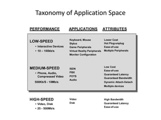
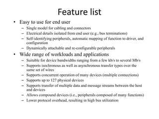
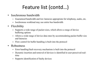
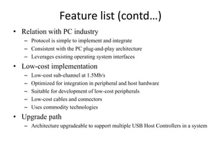
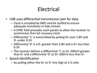
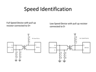
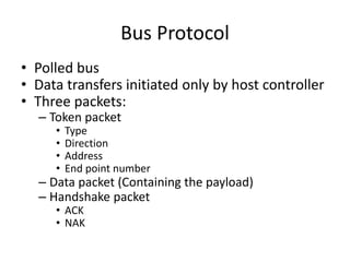
USB
Universal Serial Bus
Motivations
• Connection of the PC to Telephone
– The USB provides a ubiquitous link that can be used
across a wide range of PC-to-telephone interconnects.
• Ease of use
• Hot plug
• Port expansion
– The lack of a bi-directional, low-cost, low-to-mid
speed peripheral bus has held back the creative
proliferation of peripherals such as
telephone/fax/modem adapters, answering machines,
scanners, PDA’s, keyboards, mice, etc.
USB
• Fast
• Bi-directional
• Isochronous
• Low-cost
• Dynamically attachable serial interface
• Consistent with the requirements of the PC
platform of today and tomorrow
Goals for USB
• The following criteria were applied in
defining the architecture for the USB:
– Ease-of-use for PC peripheral expansion
– Low-cost solution that supports transfer rates up to 12Mb/s
– Full support for real-time data for voice, audio, and compressed video
– Protocol flexibility for mixed-mode isochronous data transfers and
asynchronous messaging
– Integration in commodity device technology
– Comprehension of various PC configurations and form factors
– Provision of a standard interface capable of quick diffusion into product
– Enabling of new classes of devices that augment the PC’s capability.
Taxonomy of Application Space
Feature list
• Easy to use for end user
– Single model for cabling and connectors
– Electrical details isolated from end user (e.g., bus terminations)
– Self-identifying peripherals, automatic mapping of function to driver, and
configuration
– Dynamically attachable and re-configurable peripherals
• Wide range of workloads and applications
– Suitable for device bandwidths ranging from a few kb/s to several Mb/s
– Supports isochronous as well as asynchronous transfer types over the
same set of wires
– Supports concurrent operation of many devices (multiple connections)
– Supports up to 127 physical devices
– Supports transfer of multiple data and message streams between the host
and devices
– Allows compound devices (i.e., peripherals composed of many functions)
– Lower protocol overhead, resulting in high bus utilization
Feature list (contd…)
• Isochronous bandwidth
– Guaranteed bandwidth and low latencies appropriate for telephony, audio, etc.
– Isochronous workload may use entire bus bandwidth
• Flexibility
– Supports a wide range of packet sizes, which allows a range of device
buffering options
– Allows a wide range of device data rates by accommodating packet buffer size
and latencies
– Flow control for buffer handling is built into the protocol
• Robustness
– Error handling/fault recovery mechanism is built into the protocol
– Dynamic insertion and removal of devices is identified in user-perceived real-
time
– Supports identification of faulty devices
Feature list (contd…)
• Relation with PC industry
– Protocol is simple to implement and integrate
– Consistent with the PC plug-and-play architecture
– Leverages existing operating system interfaces
• Low-cost implementation
– Low-cost sub-channel at 1.5Mb/s
– Optimized for integration in peripheral and host hardware
– Suitable for development of low-cost peripherals
– Low-cost cables and connectors
– Uses commodity technologies
• Upgrade path
– Architecture upgradeable to support multiple USB Host Controllers in a system
USB System Description
• USB interconnect
• USB devices
• USB host
USB Interconnect
• Manner in which devices are connected and
communicating with the host
– Bus topology
• Connection between USB devices and host
– Inter-layer Relationship
• USB tasks are performed at each layer in system
– Data Flow Models
– USB Schedule
• Access to interconnect is scheduled to support isochronous
data transfer
• To eliminate arbitration overhead
USB Devices & Host
• Hubs – provide additional attachment points
to USB
• Functions – provide capabilities to the system
– e.g. ISDN connection, a digital joysticks
• USB Host
– Only one host
– Interact with USB device through host controller
BUS Topology
Peripherals
1. USB host with host
controller
2. 2-port root hub integrated
into the host controller
3. 4-port hub integrated into
the keyboard (part of the
compound device)
4. USB keyboard (part of the
compound device)
5. USB keypad (part of the
compound device)
6. 4-port hub (part of the 7-
port hub)
7. 4-port hub (part of the 7-
port hub)
8. USB mouse
9. USB flash drive
10. 4-port hub
11. 4-port hub
12. USB bluetooth adapter
Peripherals Shown Explicitly
Physical Interface
pin Name Descryption
1 Vcc +5 Vdc
2 D- Data-
3 D+ Data+
4 GND Ground
Throughput
• Low speed
– 1.5 Mbps
• Full speed
– 12 Mbps
• High speed (in USB 2.0)
– 480 Mbps
• Dynamic mode switching
• Clock encoding scheme: NRZI (Non Return to Zero
Invert)
Electrical
• USB uses differential transmission pair for data
– Clock is encoded by NRZI and bit stuffed to ensure
adequate transitions in data stream
– A SYNC field precedes each packet to allow the receiver to
synchronize their bit recovery clock
– Differential ‘1’ is transmitted by pulling D+ over 2.8V and
D- under 0.3V
– Differential ‘0’ is a D- greater than 2.8V and a D+ less than
0.3V
– The receiver defines a differential ‘1’ as D+ 200mV greater
than D- and a differential ‘0’ as D+ 200mV less than D-
• Speed Identification
– by pulling either the D+ or D- line high to 3.3 volts
Speed Identification
Full Speed Device with pull up
resistor connected to D+
Low Speed Device with pull up resistor
connected to D-
Power Distribution
• Devices:
– Bus-powered devices
• Low-power Bus Powered
– Draw all its power from VBUS and cannot draw any more than one unit load (100 mA)
– Designed to work down to a VBUS voltage of 4.40V and up to a maximum voltage of 5.25V
• High power bus powered
– draw all its power from the bus and cannot draw more than one unit load until it has
been configured after which it can then drain 5 unit loads (500mA Max)
– When operating at a full unit load, a minimum VBUS of 4.75 V is specified with a maximum
of 5.25V
• Self-powered devices
– draw up to 1 unit load from the bus and derive the rest of it’s power from an external
source
– Upon failure of external source , it must have provisions in place to draw no more than 1
unit load from the bus
• Power management
– Host based
– Power events:
• Suspend
• Resume
Bus Protocol
• Polled bus
• Data transfers initiated only by host controller
• Three packets:
– Token packet
• Type
• Direction
• Address
• End point number
– Data packet (Containing the payload)
– Handshake packet
• ACK
• NAK
Protocol Layer
• Bottom-up view of the USB protocol
– Byte/Bit Ordering
– SYNC Field
– Packet Field Formats
• PID Field
• Address Field
• Frame Number Field
• Data Field
• CRC
– Packet Formats
• Token Packets
• Split Transaction Special Token Packets
• Start-of-Frame Packets
• Data Packets
• Handshake Packets
Byte/Bit Ordering
• Bits are sent onto the bus
– LSB first, MSB last
• Multiple bytes are interpreted
– Little endian order, i.e., LSB to MSB
Endian Order
• Little Endian
– The low-order byte of the number is stored in memory at the lowest
address, and the high-order byte at the highest address (The little end
comes first)
– Example, a 4 byte Long Int
• Byte3 Byte2 Byte1 Byte0
– Will be arranged in memory as follows
• Base Address+0 Byte0
• Base Address+1 Byte1
• Base Address+2 Byte2
• Base Address+3 Byte3
• Big Endian
– Will be arrange in memory as follows
• Base Address+0 Byte3
• Base Address+1 Byte2
• Base Address+2 Byte1
• Base Address+3 Byte0
SYNC Field
• Synchronization field
• All packets begin with SYNC field
• Align incoming data with the local clock
• Length
– 8 bits for full/low speed
– 32 bits for high speed
• Serves only synchronization mechanism
• The last two bits are a marker of the end of the SYNC
field
Packet Field Formats
• Field formats for
– Token packets
– Data packets
– Handshake packets
• SOP / EOP
– All packets have distinct Start-Of-Packet (SOP) and
End-Of-Packet (EOP) delimiters
PID (Packet IDentifier Field)
• Immediately follows the SYNC field of every USB packets
• Indicates the type of packet
• A PID consists of
– 4 bits packet type field
• Packet format, error type
– 4 bits check field
• Complements of the their respective packet identifier bits
PID (Packet IDentifier Field)
• The host and all functions must perform a complete
decoding of all received PID fields
• Any PID received with a failed check field or which
decodes to a non-defined value is assumed to be
corrupted  ignored by the packet receiver
• Valid PID for a transaction but does not support, the
function must not respond
– IN-only endpoint must ignore an OUT token
PID Types
Address Fields
• Function endpoints are addressed using two
fields
– The function ADDRess field (ADDR)
– The ENDPoint field (ENDP)
Address Field (ADDR)
• Specifies the function via its address
• Either the source or destination of a data packet,
depending on the value of the token PID
• 128 addresses are specified as ADDR<6:0>
• Function address zero is reserved as the default
address
Endpoint Field (ENDP)
• More flexible addressing of functions in which more
than one endpoint is required
• Is defined for IN, SETUP, OUTPUT and PING token
• Device Endpoint:
– A uniquely addressable portion of a USB device that is the
source or sink of information in a communication flow between
the host and device
Frame Number Field
• 11-bit field that is incremented by the host on
a per-frame basis
• Maximum value of 7FFh and rolls over after
reaching its maximum value
Data Field
• Data packet size varies with the transfer
type
• May range from zero to 1,024 bytes
• Data bits within each bytes are shifted out
LSB first
CRC-Cyclic Redundancy Checks
• CRCs are used to protect all non-PID fields in
token and data packets
• Token and data packet CRCs provide 100%
coverage for all single and double bit errors
Packet Formats
• Token packets
• Data packets
• Handshake packets
Token Packets
• PID
– IN, OUT, or SETUP
• ADDR / ENDP
– For OUT, SETUP
• Identify the endpoint that will receive the subsequent Data packet
– For IN
• Identify which endpoint transmit a Data packet
– For PING
• Identify which endpoint will respond with a handshake packet
• A five bit CRC that covers that address and endpoint fields
Split Transactions
• A high speed split transaction is used only
between the host controller and a hub when
the hub has full/low speed devices attached to
it
• Only defined to be used between the host
controller and a hub
• No other high speed or full/low speed devices
ever use split transactions
Split Transaction Special Token Packets
• SPLIT
– A special token for split transaction
– 4 byte token packets
• Other normal 3 byte token packets
– Provides additional transaction types with its specific information
– Is used to support split transactions between the host controller
communicating with a hub operating at high speed with full/low speed
devices to some of its downstream facing ports
• SSPLIT / CSPLIT
– Start SPLIT transaction
– Complete SPLIT transaction
Packets in a split Transaction
Relationship of Interrupt IN Transaction to High-
speed Split Transaction
Relationship of Interrupt OUT Transaction to
High-speed Split OUT Transaction
Start-Split (SSPLIT) Transaction Token
• SC (Start/Complete)
– Zero indicates that this is a start-split transaction (SSPLIT)
• Port
– The port number of the target hub for which this full/low speed
transaction is destined
Start-Split (SSPLIT) Transaction Token
• For full-speed isochronous OUT start-splits,
– S and E fields specify how the high speed data payload
corresponds to data for a full-speed data packet as show in this
table
– Allow the hub to detect various error cases due to lack of
receiving start-split transactions
Start-Split (SSPLIT) Transaction Token
• ET (Endpoint Type)
– Tells the hub which split transaction state
machine to use for this full/low speed
transaction
Complete-Split Transaction Token
• A SPLIT special token packet with the SC
field set to one
• U: reserved/unused and must be reset to
zero
Start-of-Frame Packets
• Start-of-Frame (SOF) packets are issued by the
host at a nominal rate of once every 1 ms for
full-speed bus and 125 μs for a high-
speed bus
USB Frames and Microframes
• A full speed 1 ms frame time
• A high speed microframe with a 125 μs frame time
• High speed devices see an SOF packet with the same
frame number each times during each 1 ms period
Data Packets
• Four types of data packets
– DATA0, DATA1, DATA2, MDATA
Handshake Packets
• Used to report the status of a data transaction
• ACK
– The data packet was received without bit stuff or CRC errors over the
data field and that the data PID was received correctly
• NAK
– Unable to accept data from the host (OUT) or has no data to transmit
to the host (IN)
• STALL
– Unable to transmit or receive data or a control pipe request is not
supported
• NYET and ERR
– High speed only handshake
Transfer Model
• Pipe
– Stream pipes
• No USB standard format
– Message pipes
• USB format
– Request
– Data
– Status
• End point zero
– Default control pipe
– Always exists
Data Flow Types
• Control Transfers:
– Used to configure a device at attach time and can be used for other device-specific
purposes, including control of other pipes on the device.
• Bulk Data Transfers:
– Generated or consumed in relatively large and bursty quantities.
• Interrupt Data Transfers:
– Used for characters or coordinates with human-perceptible echo or feedback response
characteristics.
• Isochronous Data Transfers:
– Occupy a pre-negotiated amount of USB bandwidth with a pre-negotiated delivery latency.
(Also called streaming real time transfers).
USB Devices
• All have endpoint zero
• Hub
• Function
• Compound
Typical Configuration
Host Responsibility
• Detecting the attachment and removal of USB devices
• Managing control flow between the host and USB devices
• Managing data flow between the host and USB devices
• Collecting status and activity statistics
• Providing power to attached USB devices.
Implementer Viewpoints
• USB Physical Device: A piece of hardware on the end of a USB cable
that performs some useful end user function.
• Client Software: Software that executes on the host, corresponding to a
USB device. This client software is typically supplied with the
operating system or provided along with the USB device.
• USB System Software: Software that supports the USB in a particular
operating system. The USB System Software is typically supplied with
the operating system, independently of particular USB devices or
client software.
• USB Host Controller (Host Side Bus Interface): The hardware and
software that allows USB devices to be attached to a host.
Control Transfer Format
• Setup packet
• Data packet
• Acknowledge packet
• USB defined structure
• Setup packet: 8 bytes
• Maximum data payload size:
– Full speed: 8, 16, 32 or 64 bytes
– Low speed: 8 bytes
Control Transfer Constraints
• Best effort
• 10% frame time for control
• Use also remaining 90% if no interrupt or
isochronous transfer
Isochronous Transfers
• Guaranteed access to USB bandwidth with
bounded latency
• Guaranteed constant data rate through the pipe
as long as data is provided to the pipe
• In the case of a delivery failure due to error, no
retrying of the attempt to deliver the data.
• Stream pipe
– Uni-directional
– Maximum data payload: 1023 bytes
– Only in Full speed.
– No more 90% of frame for isochronous, interrupt
Bulk Transfers
• Large amount of data.
• Access to the USB on a bandwidth-available
basis.
• Retry of transfers, in the case of occasional
delivery failure due to errors on the bus.
• Guaranteed delivery of data, but no guarantee of
bandwidth or latency.
• Stream pipe
• Only in full speed
• Max. Payload: only 8, 16, 32 or 64 bytes
Connectors
Full Speed CMOS Driver
NRZI Encoding
Bit Stuffing
Signaling Levels