Downloaded 17 times
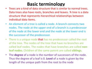


![Representation of a binary tree in memory:
• Linked representation of binary trees
• Binary trees can be represented by links, where each node
contains the address of the left child and the right child.
These addresses are nothing but kinds to the left and right
child respectively. A node that does not have a left or a
right child contains a NULL value in its link fields.
• Linked representation uses three parallel arrays, INFO, LEFT
and RIGHT and a pointer variable ROOT. Each node N of T
will correspond to a location K such that –
• INFO[K] contains the data at node N
• LEFT[K] contains the location of left child node N
• RIGHT[K] contains the location of right child node N
• ROOT will contain the location of root R of T](https://image.slidesharecdn.com/tree-180808153126/85/Tree-11-320.jpg)


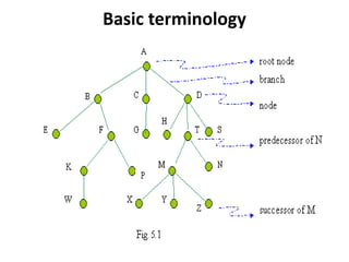
![Representation of a binary tree in memory:
• Linked representation of binary trees
• Binary trees can be represented by links, where each node
contains the address of the left child and the right child.
These addresses are nothing but kinds to the left and right
child respectively. A node that does not have a left or a
right child contains a NULL value in its link fields.
• Linked representation uses three parallel arrays, INFO, LEFT
and RIGHT and a pointer variable ROOT. Each node N of T
will correspond to a location K such that –
• INFO[K] contains the data at node N
• LEFT[K] contains the location of left child node N
• RIGHT[K] contains the location of right child node N
• ROOT will contain the location of root R of T](/p?url=https%3A%2F%2Fimage.slidesharecdn.com%2Ftree-180808153126%2F85%2FTree-11-320.jpg&__src=https%3A%2F%2Fwww.slideshare.net%2Fslideshow%2Ftree-109090192%2F109090192&__type=image)


The document discusses various concepts related to trees as data structures, particularly focusing on binary trees, their representation, and traversal methods. It covers binary tree terminology, types like complete and extended binary trees, and algorithms such as Huffman's for building trees with minimal weighted path lengths. Additionally, it explains traversal techniques including preorder, inorder, and postorder, alongside linked and array representations of binary trees.