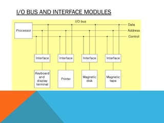
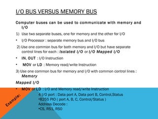
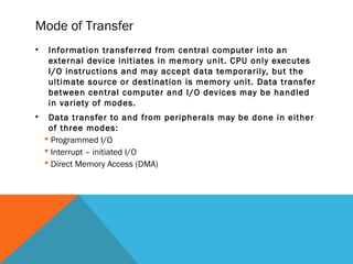
TION
                                ZA
                            A NI
                        G
                    T OR
             T PU
      T-OU
   PU
IN
6.1, 6.2 Peripheral Devices
•   Ever y time a key is depressed, the terminal sends a
    binar y coded character to the computer. When input
    information is transferred to the processor via a
    keyboard, the processor will be idle most of time while
    waiting for info To arrive.
•   Devices are said to be connected online that are
    under the direct control of the computer. These
    devices are designed to read information into or out of
    memor y unit when CPU gives a command. Input or
    output devices connected to the computer are also
    called peripherals.
•   Common peripherals are keyboard, displays units and
    printers.
•   Peripherals that provide auxiliar y storage for system
    are magnetic disk
6.3    INTERFACE – Difference between computer and
     peripherals

   A conversion of signal values may be required
     » CPU (Electronics) / HDD (Electromechanical and Electromagnet)
   A synchronization mechanism may be needed
     » The data transfer rate of peripherals is usually slower than the transfer rate of
         the CPU
   Data codes and formats in peripherals differ from the word format in the CPU and
      Memory
   The operating modes of peripherals are different from each other : 4 modes
     » Each peripherals must be controlled so as not to disturb the operation of other
      peripherals connected to the CPU


• Special hardware components between the CPU and peripherals
• Supervise and Synchronize all input and output transfers
I/O BUS AND INTERFACE MODULES
I/O BUS VERSUS MEMORY BUS
     Computer buses can be used to communicate with memor y and
       I/O
     1) Use two separate buses, one for memory and the other for I/O
     •   I/O Processor : separate memory bus and I/O bus
      2) Use one common bus for both memory and I/O but have separate
         control lines for each : Isolated I/O or I/O Mapped I/O
     •   IN, OUT : I/O Instruction
     •    MOV or LD : Memory read/write Instruction
     3) Use one common bus for memory and I/O with common control lines :
         Memor y
     Mapped I/O
     •        MOV or LD : I/O and Memory read/write Instruction
            :         4 I/O port : Data port A, Data port B, Control,Status
       p le           •8255 PIO ( port A, B, C, Control/Status )
     m
E xa                  Address Decode :
                      •CS, RS1, RS0
EXAMPLE OF I/O INTERFACE
6.4 Data Transfer Techniques
ASYNCHRONOUS DATA TRANSFER
Synchronous Data Transfer
•   All data transfers occur simultaneously during the occurrence of
    a clock pulse
•   Registers in the inter face share a common clock with CPU
    registers
Asynchronous Data Transfer
•   Internal timing in each unit (CPU and Interface) is independent
•   Each unit uses its own private clock for internal registers
STROBE


                                                                                  Destination-initiated strobe
   Source-initiated strobe


Strobe : Control signal to indicate the time at which data is being transmitted
1) Source-initiated strobe             2) Destination-initiated strobe
HANDSHAKING
•   For data transfer between two computers, the sending and receiving
    speeds on both ends are often different. Therefore, a mechanism is
    needed to make sure that the sender does not send a new byte before
    the previously sent byte is received by the receiver.
•   Even when the sender and receiver operate at the same speed, the
    sender may still want to know whether the receiver has indeed received
    the information. Handshaking provides a mechanism for addressing this
    issue. 
•    Handshaking usually uses two additional hardware lines, one is called
    “strobe” and the other is called “acknowledge”. The sender provides the
    signal to the strobe line and the receiver provides the signal to the
    acknowledge line.
•   Handshaking can be used in both parallel data transfer and serial data
    transfer.
ASYNCHRONOUS SERIAL TRANSFER
Synchronous transmission :
» The two unit share a common clock frequency
» Bits are transmitted continuously at the rate dictated by the clock
    pulses
 􀁺 Asynchronous transmission :
» Special bits are inser ted at both ends of the character code
» Each character consists of three par ts :
 􀁺 1) star t bit : always “0”, indicate the beginning of a character
 􀁺 2) character bits : data
 􀁺 3) stop bit : always “1”
ASYNCHRONOUS TRANSMISSION RULES : NO
                 PARITY
» When a character is not being sent, the line is kept in
   the 1-state
»The initiation of a character transmission is detected
   from the star t bit, which is
always “0”
»The character bits always follow the star t bit
» Af ter the last bit of the character is transmitted, a stop
   bit is detected when the line
returns to the 1-state for at least one bit time (stop bits :
   1, 1.5, 2)
Asynchronous Communication Interface
•   On Board ..
Mode of Transfer
•   Information transferred from central computer into an
    external device initiates in memor y unit. CPU only executes
    I/O instructions and may accept data temporarily, but the
    ultimate source or destination is memor y unit. Data transfer
    between central computer and I/O devices may be handled
    in variety of modes.
•    Data transfer to and from peripherals may be done in either
     of three modes:
     Programmed I/O
     Interrupt – initiated I/O
     Direct Memory Access (DMA)
Introduction
•   Binar y information received from an external
    device is usually stored in memor y.
•     Information transferred from the central
    computer into an external device also is
    originally from the memor y.
•   Data transfer between the central computer
    and input and output devices may be handled
    in a variety of modes
Programmed I/O
•   These operations are a results of I/O instructions
    written in the computer program. Data transfer is
    initiated by an instruction in the program.

•   Usually the data transfer data between CPU register
    and peripheral device. Other instructions are used to
    transfer data transfer data between CPU and memor y.

•   The peripheral has to be constantly monitored. Once
    a data transfer is initiated, the CPU is required to
    monitor the inter face to see when a transfer can again
    be made.
Applications of programmed I/O
method
 Useful in small low speed computers.

 Used in systems that are dedicated to monitor a device
  continuously.

 Used in the data register.

 Used to check the status of the flag bit and branch.
Interrupt initiated I/O
•   in this scheme, CPU may allow devices to send a
    signal when input is waiting to be processed. The
    signal is used to interrupt the CPU.


•   Interrupt signal are seen directly (using hardware) to
    micro-processor which may or may not ignore interrupt
    request. When request is granted, CPU will suspend its
    current program execution, execute an interrupt
    handler program and then resume execution of the
    interrupted program
•   Interrupted initiated I/O can be avoided by using an
    interrupt facility and special commands to inform the
    inter face to issue an interrupt request signal when the data
    are available from the device.

•   Meanwhile, CPU can proceed to execute another program.
    The inter faces keeps monitoring the device.

•   When the inter face determines that the device is ready for
    data transfer, it generates an interrupt request to the
    computer.
Service routines of Interrupt
initiated I/O
Ser vice routines of interrupt initiated I/O can be chosen
  in two ways.

Vectored interrupt

Non-vectored interrupt
Direct Memor y Access (DMA)
•    The inter face transfer data into and out of the memor y unit through
     the memor y bus.

•    The CPU initiates the transfer of supplying the inter face with the
     star ting address and the number of words needed to be transferred
     and then proceed to execute other tasks.

•    When the request is granted by the memor y controller, the DMA
     transfer the data directly into memor y. The CPU delays its memor y
     access operation to allow the direct memor y I/O transfer.
I/O Processor
•   Many computers combines the inter face logic with the requirements
    for direct memor y access into one unit and call it an I/O processor.
    The IOP can handle many peripherals through a DMA and interrupt
    facility. The computer is divided     into three separate modules in
    such a system.
   Memor y unit
   CPU
   IOP

•   CPU is the master while the IOP is a slave processor. The CPU
    per forms the tasks of initiating all operations.

•   The operations include

   Star ting an I/O transfer

    Testing I/O status conditions needed for making decisions on
    various I/O activities.
I/O Interrupts
Priority
   - Determines which interrupt is to be ser ved first
     when two or more requests are made simultaneously
   - Also determines which interrupts are permitted to
     interrupt the computer while another is being ser viced
   - Higher priority interrupts can make requests while
     ser vicing a lower priority interrupt
Priority Interrupt by Sof tware (Polling)
   - Priority is established by the order of polling the devices (interrupt
    sources)
   - Flexible since it is established by sof tware
   - Low cost since it needs a ver y little hardware
   - Ver y slow

Priority Interrupt by Hardware
   - Require a priority interrupt manager which accepts
     all the interrupt requests to determine the highest priority request
   - Fast since identification of the highest priority
     interrupt request is identified by the hardware
   - Fast since each interrupt source has its own interrupt vector to
    access
      directly to its own ser vice routine
HARDWARE PRIORITY INTERRUPT - DAISY-CHAIN -
                           Processor data bus
          VAD 1                VAD 2          VAD 3                           * Serial hardware priority function
       Device 1               Device 2       Device 3                         * Interrupt Request Line
                                                        To next
    PI       PO            PI      PO      PI      PO
                                                        device
                                                                                        - Single common line
                                                                              * Interrupt Acknowledge Line
                                                                                        - Daisy-Chain
                       Interrupt request                     INT
                                                                CPU
                       Interrupt acknowledge
                                                             INTACK

Interrupt Request from any device(>=1)
  -> CPU responds by INTACK <- 1
  -> Any device receives signal(INTACK) 1 at PI puts the VAD on the bus
Among interrupt requesting devices the only device which is physically closest
to CPU gets INTACK=1, and it blocks INTACK to propagate to the next device
One stage of the daisy chain priority arrangement
                          Priority in                              VAD
                  PI                                Enable
                                                             Vector address
       Interrupt                                         Priority out                     PI RF PO Enable
                                     RF                                       PO          0 0    0   0
        request            S     Q
    from device                                                                           0 1    0   0
                           R                                                              1 0    1   0
                                                                                          1 1    1   1
                                              Delay

                                           Interrupt request to CPU
PARALLEL PRIORITY INTERRUPT
                    Interrupt register                     Bus
                                                          Buffer
            Disk           0              I0                y
          Printer          1              I1                x
                                             Priority       0
          Reader          2               I 2 encoder
                                                            0             VAD
        Keyboard           3                                0            to CPU
                                          I3
                                                            0
                                                            0
                           0             IEN        IST
                                                            0
             Mask
            register       1                                    Enable

                          2
                                                                      Interrupt
                                                                       to CPU
                           3
                                                                      INTACK
                                                                     from CPU

 IEN:   Set or Clear by instructions ION or IOF
 IST:   Represents an unmasked interrupt has occurred. INTACK enables
        tristate Bus Buffer to load VAD generated by the Priority Logic
 Interrupt Register:
    - Each bit is associated with an Interrupt Request from
       different Interrupt Source - different priority level
    - Each bit can be cleared by a program instruction
 Mask Register:
    - Mask Register is associated with Interrupt Register
    - Each bit can be set or cleared by an Instruction
INTERRUPT PRIORITY ENCODER


    Determines the highest priority interrupt when
    more than one interrupts take place

     Priority Encoder Truth table

                Inputs                  Outputs
           I0    I1       I2       I3   x   y IST     Boolean functions
           1    d     d        d        0   0   1
           0    1     d        d        0   1   1
           0    0     1        d        1   0   1    x = I0' I1'
           0    0     0        1        1   1   1    y = I0' I1 + I0’ I2’
           0    0     0        0        d   d   0   (IST) = I0 + I1 + I2 + I3
INTERRUPT CYCLE


At the end of each Instruction cycle
  - CPU checks IEN and IST
  - If IEN • IST = 1, CPU -> Interrupt Cycle

      SP ← SP - 1     Decrement stack pointer
      M[SP] ← PC      Push PC into stack
      INTACK ← 1      Enable interrupt acknowledge
      PC ← VAD        Transfer vector address to PC
      IEN ← 0                 Disable further interrupts
      Go To Fetch     to execute the first instruction
                      in the interrupt service routine
INTERRUPT SERVICE ROUTINE
              address                 Memory                            I/O service programs
                                                                    7
                              0     JMP DISK            DISK                Program to service
                              1     JMP PTR                                    magnetic disk
  VAD=00000011           3
                              2     JMP RDR             PTR                 Program to service
                              3     JMP KBD                                      line printer
                                                    8
                 1                 Main program         RDR
  KBD                                                                       Program to service
                             749   current instr.
  interrupt                  750                                              character reader
                                                                    4
                                                        KBD                 Program to service
                                       Stack
                              11                                                  keyboard
                                                        5
                     2                                          255
                                        256         Disk        256
                                        750         interrupt
                                                                6       9        10
  Initial and Final Operations
       Each interrupt service routine must have an initial and final set of
       operations for controlling the registers in the hardware interrupt system

   Initial Sequence                                             Final Sequence
    [1] Clear lower level Mask reg. bits                         [1] IEN <- 0
    [2] IST <- 0                                                 [2] Restore CPU registers
    [3] Save contents of CPU registers                           [3] Clear the bit in the Interrupt Reg
    [4] IEN <- 1                                                 [4] Set lower level Mask reg. bits
    [5] Go to Interrupt Service Routine                          [5] Restore return address, IEN <- 1
DIRECT MEMORY ACCESS

   * Block of data transfer from high speed devices, Drum, Disk, Tape
   * DMA controller - Interface which allows I/O transfer directly between
          Memory and Device, freeing CPU for other tasks
   * CPU initializes DMA Controller by sending memory
          address and the block size(number of words)
  CPU bus signals for DMA transfer


                                                               }
                                          ABUS   Address bus       High-impedence
                 Bus request   BR         DBUS   Data bus             (disabled)
                                    CPU                              when BG is
                 Bus granted   BG           RD   Read
                                            WR   Write                 enabled
Block Diagram Of DMA Controller

    Address bus

      Data bus          Data bus                        Address bus
                         buffers                          buffers


                                      Internal Bus
       DMA select      DS                             Address register
    Register select    RS
            Read       RD                            Word count register
            Write      WR   Control
                             logic
       Bus request     BR                              Control register

          Bus grant    BG
           Interrupt   Interrupt        DMA request
                                        DMA acknowledge          to I/O device
DMA I/O OPERATION
Starting an I/O
  - CPU executes instruction to
         Load Memory Address Register
         Load Word Counter
         Load Function(Read or Write) to be performed
         Issue a GO command

Upon receiving a GO Command DMA performs I/O
operation as follows independently from CPU

Input
   [1] Input Device <- R (Read control signal)
   [2] Buffer(DMA Controller) <- Input Byte; and
       assembles the byte into a word until word is full
   [4] M <- memory address, W(Write control signal)
   [5] Address Reg <- Address Reg +1; WC(Word Counter) <- WC - 1
   [6] If WC = 0, then Interrupt to acknowledge done, else go to [1]

Output
  [1] M <- M Address, R
      M Address R <- M Address R + 1, WC <- WC - 1
  [2] Disassemble the word
  [3] Buffer <- One byte; Output Device <- W, for all disassembled bytes
  [4] If WC = 0, then Interrupt to acknowledge done, else go to [1]
CYCLE STEALING

While DMA I/O takes place, CPU is also executing instructions

    DMA Controller and CPU both access Memory -> Memory Access Conflict

Memory Bus Controller

  - Coordinating the activities of all devices requesting memory access
  - Priority System

    Memory accesses by CPU and DMA Controller are interwoven,
       with the top priority given to DMA Controller
    -> Cycle Stealing

Cycle Steal

    - CPU is usually much faster than I/O(DMA), thus
       CPU uses the most of the memory cycles
    - DMA Controller steals the memory cycles from CPU
    - For those stolen cycles, CPU remains idle
    - For those slow CPU, DMA Controller may steal most of the memory
       cycles which may cause CPU remain idle long time
DMA TRANSFER


                         Interrupt
                                                                         Random-access
                         BG
                                      CPU                                memory unit (RAM)
                         BR
                          RD    WR       Addr     Data                   RD   WR   Addr   Data
                                                     Read control
                                                         Write control
                                                         Data bus
                                                         Address bus

               Address
                select

                         RD    WR        Addr     Data
                         DS                                      DMA ack.

                         RS            DMA                                             I/O
                                     Controller                                    Peripheral
                         BR                                                          device
                         BG                                   DMA request
                         Interrupt
INPUT/OUTPUT PROCESSOR - CHANNEL -
   Channel

      - Processor with direct memory access capability
        that communicates with I/O devices
      - Channel accesses memory by cycle stealing
      - Channel can execute a Channel Program
          - Stored in the main memory
          - Consists of Channel Command Word(CCW)
          - Each CCW specifies the parameters needed
                 by the channel to control the I/O devices and
                 perform data transfer operations
      - CPU initiates the channel by executing an
        channel I/O class instruction and once initiated,
        channel operates independently of the CPU
                                           Central
                                         processing
                                         unit (CPU)
                            Memory Bus


                                                             Peripheral devices
              Memory
                unit                                    PD       PD        PD     PD

                                         Input-output
                                          processor
                                             (IOP)               I/O bus
CHANNEL / CPU COMMUNICATION


            CPU operations              IOP operations
              Send instruction
              to test IOP.path
                                         Transfer status word
                                              to memory
            If status OK, then send
                start I/O instruction
                        to IOP.             Access memory
                                            for IOP program

              CPU continues with
               another program           Conduct I/O transfers
                                              using DMA;
                                         Prepare status report.


                                         I/O transfer completed;
                                              Interrupt CPU
               Request IOP status

                                          Transfer status word
             Check status word             to memory location
             for correct transfer.


                  Continue