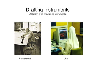
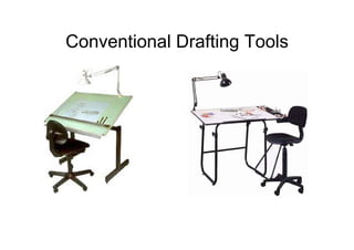
Engineering Graphics  Engg - 1 Drafting Instruments Ismael M. Quiazon
Drafting Instruments  A Design is as good as its instruments  A engineering drawing is a highly stylized graphic representation of an idea. The idea might be of something that we can see such a real or virtual object, space or environment. In some cases, such as an electronic schematic diagram for example, the drawing will bear no visual resemblance to the physical object that will be built from the information it provides.
Drafting Instruments  A Design is as good as its instruments  Conventional  CAD
Conventional Drafting Tools
Drawing Board  Drawing Table  Drafting Board
Drawing Board  ‰   Available in a variety of styles and sizes.  Most are adjustable up and down, and can tilt to almost any angle from vertical 90 o  to horizontal  ‰   The drawing surface must be clean, flat, smooth, and large enough to accommodate the drawing and some drafting equipment.  ‰   If a T-square is to be used, at least one edge on the board must be absolutely true.  ‰   Most quality boards have a metal edge to ensure against warping  and to hold the T-square securely  Drawing Table with a  Drafting machine
T-Square  ‰   It provides a parallel straight edge for the beginning  drawing drafter.  ‰   It is composed of two parts: the  head and the blade.  The two parts are  fastened together at an exact right angle.  ‰   The blade must be straight and free of any necks and  imperfections.
T-Square  ‰   Used to draw horizontal lines on the drawing  sheet.  ‰   Used to draw vertical lines and slanted lines with the help of additional  equipment basically 45 o  and 60 o  triangles.  ‰   Draw lines only against the upper edge of the blade.  Make sure the head is held against the left edge of the drawing board to guarantee parallel lines.  ‰   Use a T-square to align the drawing paper to the drawing board, and to draw parallel horizontal lines on the paper.
Parallel Straight Edge  ‰   A parallel straightedge is a laminated maple blade with transparent  plastic  edges similar  to those on the T square. Its  primary  purpose is the same as the T square.  ‰   The parallel straightedge uses a  system  of  cords  and  pulleys  so  that  it  is  supported  at  both  ends  by a  cord  tacked  to  the drawing board.  ‰   You  can  move  the straightedge up or down the board with pressure at any point along  its  length  and maintain  parallel  motion automatically.
Parallel Straight Edge  ‰   The straightedge is locked into place by turning the cord lock clockwise. This permits use of the straightedge on an inclined board. It also prevents accidental movement when you are inking or using mechanical lettering devices.  ‰   The advantages of the parallel straight- edge become particularly significant when you are working on large drawings. While the T square works well for small work, it becomes unwieldy and inaccurate when you are working on the far right-hand side of large drawings
Drafting Machine  ‰   The standard drafting machine combines the functions  of  a parallel  ruler,  protractor, scales, and  triangles. Various drafting  operations requiring straight  and  parallel  lines may  be performed  advantageously  with  a drafting machine.  ‰   The  majority  of  drafting machines are constructed  so that  the  protractor  head  may be moved over the surface of a drafting table without change in  orientation  by  means  of  a parallel- motion  linkage.
Drafting Machine  ‰   A drafting machine is a device that attaches to the drafting table and replaces the T-square, triangles and protractors.  ‰   They increase the accuracy and greatly reduce drafting time.  ‰   Most drafting machines have a protractor and a vernier which permits reading to 5 minutes of an arc.
Drafting Machine
Pivot Compass  ‰   A compass is used mainly to draw circles and circular curves of relatively short radius .  ‰   The large pivot joint compass is satisfactory for drawing circles of 25 mm to about 300 mm in diameter without  an  extension bar.  ‰   The  pivot  joint  provides enough friction  to  hold  the  legs  of  the compass in a set position. One of the legs is equipped with a setscrew for mounting either a pen or a pencil attachment on the compass.  ‰   The metal point extends slightly more than the lead to  compensate for the distance the point penetrates the paper.
Bow Compass  ‰   The  other  type  of  compass is  the  bow  compass.  Many experienced draftsmen prefer the bow compass over the pivot joint compass.  ‰   The bow compass is much sturdier and is capable of taking the heavy pressure necessary to produce opaque pencil lines without losing the radius setting.  ‰   Most  compasses  have interchangeable  needle- points.  The  conical  or  plain needlepoint  is  used when the  compass  is  used  as dividers.
Extension Bars  ‰   Extension bars are available for large bow compasses to draw large diameter circles.
Using the compass to draw a circle  To draw a circle with the bow compass, the compass is revolved between the thumb and the index finger.
Compass Center Disk  ‰   When many circles  are drawn using the same center, the compass needle may tend to bore an  oversized hole in the drawing. To prevent these holes, use a device called a horn center or center disk. This disk is placed over the center point. The  point  of  the compass  needle  is then placed  into  the hole  in  its  center
Divider  ‰   Dividers  are  similar  to  compasses,  except that both  legs  are  provided  with  needle points.  ‰   As with compasses, dividers  are  available  in large  and  small sizes,  and  in  pivot  joint,  and bow types.  ‰   Pivot  joint  dividers  are  used  for measurements of  approximately  20 mm or more.  ‰   For  measurements of  less  than 20 mm, bow dividers  should  be used.  ‰   Dividers are used to transfer measurements. to step off a series of equal distances, and to divide lines  into  a  number  of  equal  parts  ‰   A divider is similar to a compass, except that it has a metal point on each leg.  ‰   It is used to lay off distances and to transfer measurements.
Triangles  ‰   Triangles  are  used  in  combination with the T square or straightedge to draw vertical and inclined  lines. They  are  usually  made  of transparent plastic, which allows you to see your work underneath the triangles.  ‰   Two standard triangles are used by the drafters.  One is the 30-60-degree triangle.  The other is the 45-degree triangle.  ‰   When laying out lines, triangles are placed firmly against the upper edge of the T-square.  Pencils are placed against the left edge of the triangle, and lines drawn upwards, away from the edge.  ‰   Parallel angular lines are made by moving the triangle to the right after each new line has been drawn.
Triangles  ‰   Triangles  are  used  in combination  with the T square or straightedge to draw vertical and inclined lines.  They  are  usually made  of transparent plastic, which allows you to see your work underneath the triangles.  ‰   Two standard triangles are used by the drafters.  One is the 30-60-degree triangle. The other is the 45-degree triangle.  ‰   When laying out lines, triangles are placed firmly against the upper edge of the T-square.  Pencils are placed against the left edge of the triangle, and lines drawn upwards, away from the edge.  ‰   Parallel angular lines are made by moving the triangle to the right after each new line has been drawn.
Triangles     To test the straightness of a triangle, place it against the T square and draw a vertical line, then  reverse the  triangle and draw another line along the same edge. If the triangle is straight, the two lines will coincide; if they don’t coincide, the error is half the resulting space
Adjustable Triangle  ‰ he  adjustable triangle combines  the functions  of  the  triangle and  the protractor.  When  it  is  used  as  a right triangle, the hypotenuse can be set and locked at any  desired  angle to  one  of  the  bases.  ‰ The transparent protractor portion is  equivalent to a protractor  graduated  in  1/2°  increments.  ‰ By holding  either  base  against  a  T-square, you can measure or draw any angle between  0°  and  90°.  ‰ he  adjustable  triangle  allows  you to  transfer  parallel  inclined  lines by sliding  the  base  along  the  T square  or straightedgeAn adjustable triangle may take place of both the 30o -  60o   and 45o   triangles.  ‰ t is recommended that this tool be used for drawing angular lines that can not be made with the two standard triangles.  The adjustable triangle is not as accurate as the solid triangle.
Drawing Templates  ‰   A template is a thin, flat piece of plastic containing various cutout shapes.  It is designed to increase the speed and accuracy of the drafter.  Circle Template  ‰   Templates are available for drawing circles, ellipses, plumbing fixtures, bolts, nuts, screw threads,  electronic symbols, springs, gears and much more.  ‰   A template should be used whenever possible to  increase the accuracy and the speed.  Ellipse Template
Drawing Templates  Nut, Bolt and Screw Template
Drawing Templates  Screw Heads Template
French Curves and Flex Curves  ‰   French curves are thin  plastic tools that come in assortment of curved surfaces.  They are used to produce curved lines that cannot be made by a compass.  ‰   Most common French curves are actually segments of ellipses, parabolas and  hyperbolas.  ‰   Adjustable curves may also be used to create a smooth curve between a set of points.
French Curves and Flex Curves
French Curves and Flex Curves  ‰   Protractors are  used for  measuring and laying  off  angles other  than  those that  may  be  drawn  with  the triangle  or  a combination  of triangles.  ‰   Like the triangle, most protractors are made of  transparent plastic.  They are  either circular or  semicircular  in shape.
French Curves and Flex Curves  ‰   To use a protractor,  place the center  point on the corner point of the angle. Align the base of the protractor along one side of the  angle.  The degrees are read along the semicircular edge.
Erasing Shield  ‰   An erasing shield restricts the erasing area so that the correctly drawn lines will not be disturbed during the erasing procedure.  ‰   It is made from a thin flat piece of metal with variously sized cutouts.  ‰   The shield is used by placing it over the line to be erased and erasing through the cutout.
OTHERS PROPERTY  First Phase  EXISTING • THREE FLOORS  live floors struct completed  PROPOSED GROUN  (cond. area on each  n  a approx  (BELOW MAS  _.T.i  1500 sqft)  J  Proposed six floor jqr  •  5)  SECOND PHA.= E (C: o NTD ...)  OROUND F LAO R STRUCTCOUPLETED (COVD. AREAON EAC H F LAPP ROX 500 so.  PRO POSED SIX F LOO RS (O R.•5)  SECO N O P HARE (CO N TO...)  EXCAVATION OF HARD ROCK  IN PROORE88  (CO VD. AREA O N EACH F L.APPROX 250 80 . FEET)  PRO POSED 8IX FLO0 R8 (OR. •5)  STUDENT'S K ITC HEN & S TO R E  STUDENT'S DINNING AREAt•...•.r. S TUDENT'S tN.C & IATHROO 1.1 •= INAZOO AREA  I.IISC.STORE.GENERATOR % Pu.NEL R TEIIP PARKING AREA  .4Mi ►.  ..1IA. 10  . •
7  r  I" y..,.�`Ill  STAIRCASE  � LOOR I  S:kE 1:40  NOTE VFR D6S  624  A 676  .�...V. dya. -.. �.y... ..`... � '  1.  77  El  � 71T'  0  achtled O  STAIRCASE  FLOOR 1  SCALE  47  S  6  FLOOR  NOTE: VER DES 624 A 626  SCALA 1:10
Scales in Engineering Drawing  On  drawing  On Site  Scale: 1=10 Scale 1:10
Metric Scales
Inches Scales
Wooden Pencils Grades  Softest  Hardest
Pencil Grades  Softest  Hardest
Pen Sizes and Line Weights  Line weights are a vital part of conventional technical  0.13  graphics language. They are embodied to the extent of being defined in national and international standards.  In  0.18  manual drafting, different pen sizes allow the drafter to  give different line weights to the lines in the drawing.  0.25  Line types and line weights allow drawings to  0.3  communicate information that would otherwise be very  difficult to convey. For example:  0.5  • Hidden outlines  0.7  • Paths of motion  1.0  • Planes of symmetry  1.2  • Fictitious outlines such as major and minor  1.4  diameters of screw threads  2.0  • Dimensions and projections  • Materials (hatching)  • Centers and imaginary intersections
Pen Sizes  Conventional practice is that only two  0.18  different line weights be used on any one  0.25  drawing. This is subject to discretion and  some disciplines regularly use three, and  0.3  occasionally four.  0.5  Different line weights. Consistency and  0.7  clarity of communication are the deciding  1.0  factors. You could use 10 line weights in a  drawing provided everyone understood  1.2  what they all meant and the document was  1.4  consistent.  2.0
Pen Sizes  Line weight groups chosen for most engineering drawings are selected from adjacent pen thicknesses (in mm). The table below indicates line weight groups for various sheet sizes. Pen thickness are shown in mm.  0.18  A4, A2, A3  0.25  0.35  A1  0.50  A0  0.70 1.00 1.40 2.00
Line Types  Line type  Thickness  Example  Application  Fine  Thick  Visible outlines, existing features, cut  Continuous thick  0.35  0.50  edges, general line work  Used where another level of line weight  Continuous medium  0.25  0.35  would assist the delineation e.g. internal  line work, notes  Fictitious outlines, imaginary  Continuous thin  0.18  0.25  intersections and projections, hatching,  dimensions, break lines  Dashed thick  0.35  0.50  Hidden outlines and edges  Dashed thin  0.18  0.25  Indication of special surface  requirements or (sometimes with a text  Chain thick  0.35  0.50  component) to indicate pipelines and services  Center lines, motion paths, indication of  Chain thin  0.18  0.25  repeated detail
LINE STANDARDS  NAME  CONVENTION  DESCRIPTION AND APPLICATION  SAMPLE  THIN LINES MADE UP OF LONG AND SHORT DASHES ALTERNATELY SPACED AND  CENTER  CONSISTENT IN LENGTH  LINES  USED TO INDICATE SYMMETRU ABOUT AN AXIS AND LOCATION OF CENTERS  HEAVY UNBROKEN LINES  VISIBLE  LINES  USED TO INDICATE VISIBLE EDGES OF AN  OBJECT  MEDIUM LINES WITH SHORT EVENLY SPACED  HIDDEN  DASHES  LINES  USED TO INDICATE CONCEALED EDGES  THIN UNBROKEN LINES  EXTENSION  USED TO INDICATE EXTENT OF DIMENSIONS  LINES  THIN LINES TERMINATED WITH ARROWS HEADS AT EACH END  DIMENSION  LINES  USED TO INDICATE DISTANCE MEASURED
Scales  Drawing Table  Adjustable Triangle