Download as PDF, PPTX


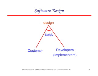


The document discusses software design and key concepts related to software design including: 1) Software design is the process of planning the architecture, components, interfaces, and other characteristics of a software system. 2) Good software design aims for high cohesion and loose coupling between modules. It involves conceptual design, technical design, and refinement of the design. 3) Modularity, coupling, and cohesion are important design principles. Modularity enhances manageability while loose coupling and high cohesion are design goals.


![[slides] Software Engineering Third Edition - Aggarwal, Singh.pdf](https://cdn.slidesharecdn.com/ss_thumbnails/slidessoftwareengineeringthirdedition-aggarwalsingh-230615025923-02cadfc5-thumbnail.jpg?width=640&height=640&fit=bounds)